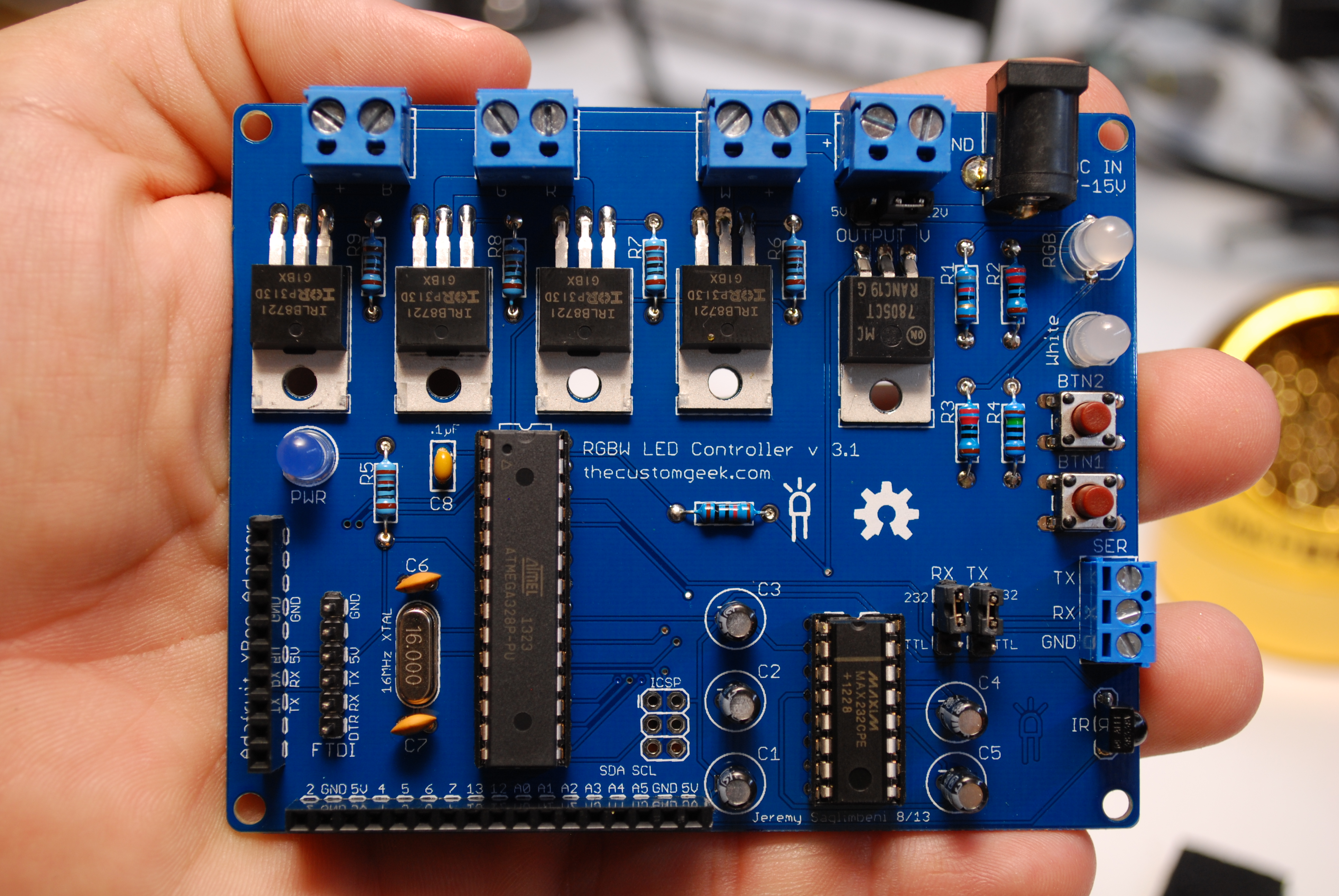
RGBW LED Control Kit – Assembly Tutorial
I now have a downloadable PDF manual with pictures and linked index! (and ver 2.2 updates!)
Note: You can click on any picture to get the full res version in a new tab.
Make sure you visit the use it page when you finish assembly.
***Version 2.2 is now shipping! – Please note the following updates below, also highlighted in red in the instructions.***
A few changes and additions for the better, but pretty much the same great board. The first change was to correctly orient the IR sensor. Secondly, there is now a screw terminal for 12V power input, as well as 5V power output for sensors, and a dedicated I2C bus along with the other pins. Finally the power traces were thickened to increase power handling. (drive more LED’s!)
Parts list - You should have received the following parts:
PCB (#1), 5 1KΩ resistors (#2), 2 220Ω resistors (#3), 1 150Ω resistor (#4), and 1 82Ω resistor (#5), 2 22pF ceramic capacitors (#6), .1µF ceramic capacitor (#7), 16MHz crystal (#8), 2 momentary push button switches (#9), ATmega328 (#10) with an Arduino bootloader, MAX232SPE (#11), DIP sockets (#12), 4 TIP122 darlington transistors (#13), 7805 voltage regulator (#14), IR sensor (#15), Female headers (#16), Male header (#17), Three jumper shunts (#18), white LED (#19), green LED (#20), RGB LED (#21), 5 .1µF electrolytic capacitors (#22), two wire terminal connector 5mm (#23), three wire terminal connector 3.5mm (#24), Two wire terminal connectors 3.5mm (#25), DC power jack (#26), and Rubber feet (#27).
Resistors - First we will put the resistors in. I personally like to cut them from the ‘tape’ they are shipped in because it eliminates any adhesive residue that might give us a headache later. I have shipped these kits with 1 extra of each value. This means you will have 4 left over resistors when you complete the assembly. (unless the dog ate one of them) If you are not familiar with 5 band resistors, the values are as follows:
82Ω – Grey, Red, Black, Black, Brown
150Ω – Brown, Green, Black, Black, Brown
220Ω – Red, Red, Black, Black, Brown
1KΩ – Brown, Black, Black, Brown, Brown
You can bend the resistor like the one. This will allow them to go into the board easily.
Next, insert it into the board to sit inside the silkscreen mark as pictured below. Note that resistors are not polarized, and it does matter witch way they are inserted.
You can slightly bend the resistor leads out, this will help keep the resistor in place when you turn the board over to solder it.
You can insert a handful of resistors, then solder them 4 or 5 at a time.
Solder them up good!
Once soldered, trim the leads with a pair of good quality diagonal cutters.
When you are done soldering and trimming, the board should look somewhat like this.
Ceramic Caps – Insert and solder the Ceramic capacitor that has the value of .1µF. There is one of these shipped with this kit and has the marking “104″ on it. Polarity does not matter with this part, you can insert it in either direction.
Next, insert and solder the .22pF capacitors, they are marked with a “22″. They are also not polarized.
Crystal – Insert and solder the crystal. Crystal are not polarized, and therefore there is no ‘wrong way’ to put them in.
Switches – This kit comes with 2 momentary tactile pushbutton switches. Insert both switches in the same direction as shown below, note that they can only be inserted in 2 out of the 4 possible directions. Either of the 2 possible directions will work fine. They will fit snugly in place.
They should look like the picture below when both inserted.
I always like to (but is not required) bend the switch leads over as follows: First, place a small flat screwdriver beside the lead.
Second, ‘fold’ the lead over by rolling the screwdriver over top of it.
It should look like this when you get done.
Rinse and repeat 7 more times. This step will prevent the leads from poking out too far of the bottom of the board and help secure the switches on the board.
ATmega328 Socket - Now let’s insert the 28 pin socket for the microcontroller. Notice the notch at one end of the socket. This must line up with the notch that is silkscreened on the board as pictured below.
We can do the same lead bending trick as we did with the switches. This will help us keep a low profile as well as keep the socket in place while we turn the board over to solder it in place.
MAX232CPE Socket - We will keep in observance the same notch at the top of the socket as the previous one.
Next, fold the pins over like we did in when installing the previous socket.
LED’s - Let’s install some blinky! Notice on the LED’s that one lead is longer than the other. This is the anode or positive lead. Also notice that the LED has a ‘flat spot’ on one of the side where the shorter lead is. This side is the cathode or negative side. Insert the LED’s with the longer lead away from the ‘flat spot’ on the silkscreen.
This means when the LED is inserted, the ‘flat spots’ should line up. Solder and trim the white LED into place.
Next insert the RGB LED. Notice it has 4 leads, but still has a ‘flat spot’. Line up the ‘flat spot’ and insert as pictured below.
With the RGB LED installed correctly, solder and trim the LED leads.
Next, insert the power LED.
After verifying the LED is inserted the correct way, solder and trim the leads.
TIP122 Darlington Transistors’s - Next we will install the 4 TIP122 Darlington Transistors. MAKE SURE YOU USE THE TIP122′s AND NOT THE 7805! Installing them is pretty straight forward, just insert them a little way, then bend them over to lay flat on the board.
Once bent over, they should look like the picture below.
Self clamping tweezers come in very handy to hold things in place while soldering. Solder, and trim the leads next.
7805 5V Voltage Regulator - Now we will install the 7805 in the same manner we installed the TIP122′s in.
Electrolytic Caps - Next we will install the electrolytic capacitors for the MAX232CPE. These are polarized and need to be inserted with the shorter lead going to the negative side on the board. Note that one of the caps gets installed in the opposite direction as the other 4, following the silkscreen markings on the board. Install and solder C1 – C4.
Cap number 2.
Cap number 3.
Cap number 4..
And finally, cap number 5. This is the one that is installed with the longer or positive lead facing the left as pictured below. Once all caps have been inserted, solder and trim the leads.
Power Jack - Install the power jack as pictured below.
Once inserted into the board, bend the leads out and solder heavily. Make sure you use a good amount of solder as this will add strength to the jack ensuring longevity.
Serial Input/Output and LED Output Terminals - Next we will install the terminal blocks that will be the serial interface, and LED output. I found if you slightly bend the leads, the blocks tend to stay put while you solder them in.
First install the larger terminal block, it’s larger because it’s more awesome than the others I made the boards with the wrong size holes and had to order blocks that fit. They will work the same way. Once inserted, solder them in.
***UPDATE FOR VER 2.2*** The three position serial terminal block is the same size as the LED output blocks (3.5mm), there is now a larger (5mm) TWO position terminal block for power input, see the pic below for reference.
Do the same for the white LED terminal block.
For the RGBW blocks, use the 2 remaining 2 wire terminals. They will lock together with the built in dove tail style moldings on the sides.
View from the top, they will come together nicely.
Once together, they fit snug as a bug in a rug. Insert and solder them in.
Output Voltage Select Jumper Header - Now you want to trim a piece of male header to use for the output voltage selection. Use a pair of flat nose or needle nose pliers to hold 3 pins of header, and hold tightly.
Snap the remaining header bending as close to the pliers as you can. The end result should look like the picture below.
Then install the header in the board next to the “LED V” label just to the left of the 7805, and solder it into place.
Serial Type Jumper Header - Repeat the same thing twice more to get the headers for the serial type selection.
Install and solder the serial type selection headers in the board where the “TTL RS232″ labels are. The result should look like the picture below.
FTDI Header - Repeat the previous procedure to get the FTDI header, only make it a 6 pin header instead of 3.
Install and solder the FTDI header on the board where the label “FTDI” is. The result should look like the picture below.
XBee Female Header - Count 10 female sockets, and the cut the NEXT (11th) one. You have to sacrifice 1 slot to trim this type of header. You can cut these carefully with a pair of diagonal cutters.
SNAP! A clean break is a happy break.
The remaining female header should have 10 slots in tact for the optional XBee adaptor.
Insert the female XBee header in the board where the label “Adafruit XBee” is, then solder it in place.
ATmega328 Pin Extension Header - Repeat the step to trim the female header, just make this one 12 slots, so you will cut on the 13th slot.
Be sure and to cut straight and not cut into the next slots.
Next, insert the female header and solder it into place. The result should look like the picture below.
IR Sensor - Next, install the IR sensor. Notice the sensor is bent over to face the outside. This is because it is a new awesome method that has not caught on yet I made the boards and had the sensor facing the wrong way. It will work just fine this way. Unless your application has the board mounted so it needs to receive IR from the other side, in that case, I’m a genius.
***UPDATE FOR VER 2.2*** The IR sensor is now oriented the correct way on board version 2.2 and newer. See below for the correct installation of the IR sensor. See the pic below for reference.
IR sensor from the top. (ver 1.9)
Voltage Jumper - This jumper is to select the output voltage for the LED’s. Short the center pin and 5V for 5 volts, or the center pin and 12V for 12 volts.
Serial Select Jumpers - Next short the center pin on the serial jumpers to TTL for transistor to transistor logic (5v) or 232 for RS232 (+ or – 3-15 volts).
Installing the MAX232CPE IC - Next install the MAX232CPE IC, when they are shipped from the factory, the leads are a bit wide to fit in a standard .3″ socket. The best method I have found to solve this problem is to hold the IC by the ends, lay the leads on a flat surface, and gently and slightly roll the IC bending the leads in just a tiny bit. Remember, you can always do it again if it not enough the first time.
The IC leads should look somewhat close to the picture below.
Insert the IC into the socket observing the notch in the IC lines up with the notch in the socket. It should end up like the picture below.
Installing the ATmega328 IC - Repeat the same steps as the MAX232CPE for the ATmega328, again making sure the notch in the IC and socket lines up.
Rubber Feet - Install the rubber feet on the bottom of the board to balance, secure and insulate it.
Finished! - That’s it! You’re done, you can now take control of your blinky.
Be sure and check out the page on using your new creation!
Please ask all questions in the forums, thanks!


