I needed to charge an iPad, but I couldn’t do it the “normal” way because it was stuck in a wall! I had mounted 2 iPads in walls at a customers house. I did this by cutting a big iPad sized hole in the wall, and then building a custom mounting dock for it. I also embedded an arduino bootloaded ATmega 328 in there along with a MAX3232 (RS232 to TTL) chip for controlling the iPad via RS232. Now all I had to do was keep it charged. I found Ladyada’s mintyboost resources a huge help. She even has a video on Reverse engineering Apple’s secret charging methods. With her video and mintyboost page, I was able to build a working charging circuit that has worked perfect since December of 2010.
On a side note, you may ask yourself why would anyone put an iPad in a wall? Well, it serves as a lot of cool things, but the main one is to control the home automation systems I install. And an iPad is about the same price (with my dock) as a touchscreen the automation company sells. The automation system controls HVAC, lighting, security, audio (multi room/source), video, intercom, and also have close contact output as well as 5 RS232/485 ports, Ethernet, and telco connectivity. I’ll have to show off my automation system one day, it’s really an amazingly flexible system.
Why not just use the stock iPad charger? Because I don’t do cheesy. Apple chargers are cheesy? No, of course not. I will not tolerate any wires in plain sight at a customer installation. Ever. And I have seen a number of on wall (not in wall) iPad docks that have a wire going down to an outlet. Let’s just say, that’s not my style. NEC code does not allow for exposed high voltage inside a wall, like an outlet with an Apple charger sticking out. So the answer was to build my own solution with low voltage only. For power, I used 2 5v 2A power supplies from Adafruit.
Keep in mind that an iPad charger will charge an iPhone, but an iPhone charger will not charge an iPad. At least this is what Apple tells you. The truth be told, an iPhone charger will charge an iPad when it’s asleep, but that’s at a trickle rate that is painfully slow. I say all that to say this: I’m not clamming this is the only way to charge iDevices, it’s just the way I did it. This method will charge any device currently out right now including the iPad 2.
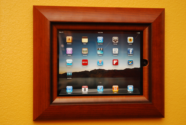
Here is a shot of the end result. The wow factor is there with authority.

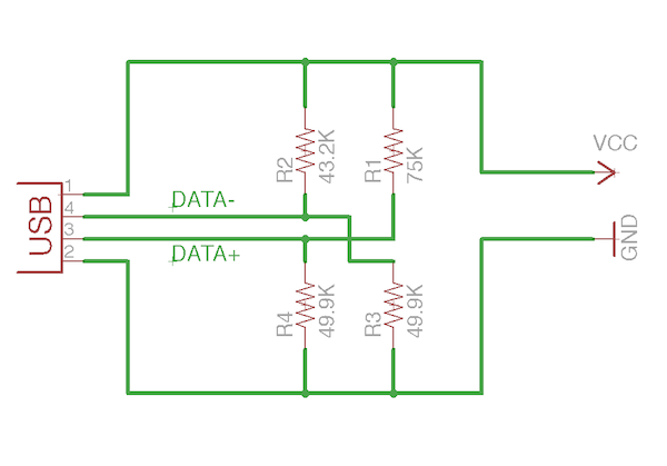
Here is the schematic:


Awesome work. Couple questions if I may?
– I’d love to see more about the wall install. Mounting, and AC.
– Did you do any research in what it takes for the ipad to draw the full 2 amp charge? Is it different resistors on the data pin? Or is it something else?
Holy crp, very impressive. That looks sweet man, nice job on the dock!
What type of automation do you do? I personally work with insteon and would love to find out what type of cool things you can do with an arduino and insteon. Is there anything that you can point me in the direction to find out if this is possible.
Great mount looks great..
Hi J. Walters, thanks for the kind words. I use HAI (Home Automation, Inc. – http://homeauto.com) systems. I love them to pieces. I plan on doing a tour of my house when I get around to it, I would really like to show it.
As far as things I’m working on right now, I am basically working with different gadgets (LED control, and touchscreen interface) that use serial control. The Omni Pro2 boards that I use have 5 serial ports, so I can have my lighting control on 1, AV receiver on another, and my Arduino controlled stuff on a second port, leaving 2 still open. I use 1 port for all my Arduino custom stuff, because I use different serial commands, so if the command is not for that device, it just ignores it. I am finalizing a really nice kit for LED control that will play nice with automation systems, I should have it ready within a month. Hope this helps!
Pingback: Electronics-Lab.com Blog » Blog Archive » Charging an iPad, iPhone, or iPod
Very well done and quite interesting. In my home I have an in wall computer in every room (they are 1.5″thick, about the same size as an iPad with their bezel, run win XPe, and have a full touchscreen, take ethernet and powered by 18vDC) I keep my home at NEC electrical code being a one time electrician. I am switching to iPads, using iDocx as the wall mount. The home is completely automated using Homeseer, aand things I have built.
I plan to use a dc-dc (15 watts, 3 amp) converter using the existing DC wiring at each location but switching to 12V source as opposed to 18. The head end has a 100 amp 12v regulated supply to power HA glue stuff. I am assuming that the iPad will “overcharge” with out the resistor network telling it the correct charging rate. Do you have any idea what will happen without the resistor network, i.e left the USB data pins floating? Since they will be always in the wall (I use Pronto PRO’s for my hand held units, as I like the buttons) I am not sure I care about battery life as long as an iPad will run with a “Dead battery”.
On a side note have you found any solution to powering down the iPad backlight or powering the iPad off programmatically?
Jeremy, There might be a market for a little USB dongle that has the resistors in it with a USB jack on one end and the other end terminating in a USB plug, a standard 2.1 mm power jack or a 2 wire header. I may be building one on a little PC breadboard for my iPad in wall efforts.
Hi Barry! Your house sounds awesome, and going to iPads will work great. If you leave the USB pins floating, the iPad will not charge. The resistors serve more as a ‘handshake’ than anything else. The iPad has internal power management, and that’s a good thing because it’s really hard to make power blunders with them as long as you never feed it over 5 volts.
As far as getting the iPad to sleep, I have made a solution for that using a microcontroller. I can control media functions, wake and sleep, and have direct audio out. I’ll do a post on that sometime, but maybe I can show you in the very need future, I was less than a mile from your house yesterday. 🙂 I live in Palm Bay FL. I’ll send you an email with details.
Pingback: i Get a charge out of this! | The Custom Geek
We make a device that does exactly this.
shop.kineteka.com/p/125/podsync-ipod-ipad-iphone-to-usb-charge-and-sync-adapter
Hi Jeremy! I’m new in your site. I’ve been reading your posts and i get a question about this post in particular.
¿The “meter program” that you mention in the video was developed by you or exists some documentation about it?
I’m working in something that requires some kind of software like that.
I hope you excuse my english, i’m from Colombia and writing english isn’t my stronger hability.
Your site is so great, really!
Thanks
Hi Joel, that meter software came with a meter that I got from Radio Shack years ago. The meter is discontinued now, but it just uses serial commands, so you might get it to work with another meter. You can download a copy of the software here: http://www.thecustomgeek.com/files/MeterView.EXE
Thanks! Jeremy. I’ll check it.
in video u said “…43.3k resistor from VCC to DATA+…” In schematic 43.3k resistor goes from VCC to DATA-. mistake in video or in circuit ?
Hey juoza, schematic is right, sorry about that. 43.2Ω goes from VCC to Data -, thanks. 😉
Hi Jeremy,
Your diagrams shows USB pin 4 is Data – but according to USB standard is this GND.
Pin 1 VCC (+5 V)
Pin 2 Data-
Pin 3 Data+
Pin 4 Ground
Hi Thomas, I used that part from the Sparkfun library, they got pins 2 and 4 mixed up, but it worked because both the schematic and board files were switched. Pin 4 should be ground, good observation. 😉